"THIRD WEEK"
is a circuit in which resistors are arranged in a chain, so the
current has only one path to take. The current is the same through each
resistor. The total resistance of the circuit is found by simply adding up the
resistance values of the individual resistors:
equivalent resistance of resistors in series : R = R1 +
R2 + R3 + ...- With simple series circuits, all components are connected end-to-end to form only one path for electrons to flow through the circuit:

·
Voltage drops add to equal total voltage.
·
All components share the same (equal) current.
·
Resistances add to equal total resistance.
·
The current is the same in every resistor; this
current is equal to that in the battery.
·
The sum of the voltage drops across the individual
resistors is equal to the voltage rating of the battery.
·
The overall resistance of the collection of
resistors is equal to the sum of the individual resistance values,
Parallel Circuits
A parallel circuit is a circuit in which the resistors are arranged with their heads connected together, and their tails connected together. The current in a parallel circuit breaks up, with some flowing along each parallel branch and re-combining when the branches meet again. The voltage across each resistor in parallel is the same.
The total resistance of a set of resistors in parallel is found by adding up the reciprocals of the resistance values, and then taking the reciprocal of the total:
equivalent resistance of resistors in parallel:
1 / R = 1 / R1 + 1 / R2 + 1 / R3 +...
With simple parallel circuits, all
components are connected between the same two sets of electrically common
points, creating multiple paths for electrons to flow from one end of the
battery to the other:


Learnings:
·
All
components share the same (equal) voltage.
·
Branch
currents add to equal total current.
·
Resistances
diminish to equal total resistance.
·
The
voltage drop is the same across each parallel branch.
·
The sum
of the current in each individual branch is equal to the current outside the
branches.
·
The
equivalent or overall resistance of the collection of resistors is given by the
equation
Analysis of Combination Circuits
The basic strategy for the analysis of combination circuits involves using the meaning of equivalent resistance for parallel branches to transform the combination circuit into a series circuit. Once transformed into a series circuit, the analysis can be conducted in the usual manner. the method for determining the equivalent resistance of parallel are equal, then the total or equivalent resistance of those branches is equal to the resistance of one branch divided by the number of branches.

This method is
consistent with the formula

1 / Req = 1 / R1 +
1 / R2 + 1 / R3 + ...
where R1,
R2, and R3 are the resistance values of the
individual resistors that are connected in parallel. If the two or more
resistors found in the parallel branches do not have equal resistance, then the
above formula must be used.
By applying one's
understanding of the equivalent resistance of parallel branches to a
combination circuit, the combination circuit can be transformed into a series
circuit. Then an understanding of the equivalent resistance of a series circuit
can be used to determine the total resistance of the circuit. Consider the
following diagrams below. Diagram A represents a combination circuit with
resistors R2 and R3placed in parallel branches. Two
4-Ω resistors in parallel is equivalent to a resistance of 2 Ω. Thus,
the two branches can be replaced by a single resistor with a resistance of
2 Ω. This is shown in Diagram B. Now that all resistors are in series, the
formula for the total resistance of series resistors can be used to determine
the total resistance of this circuit: The formula for series resistance is
Rtot = R1 +
R2 + R3 + ...
So in Diagram B,
the total resistance of the circuit is 10 Ω.
Once the total
resistance of the circuit is determined, the analysis continues using Ohm's law
and voltage and resistance values to determine current values at various
location.
General rules for series-parallel
circuits
- Two (or more) resistors with their heads
directly connected together and their tails directly connected together are in
parallel, and they can be reduced to one resistor using the equivalent
resistance equation for resistors in parallel.
- Two resistors connected together so
that the tail of one is connected to the head of the next, with no other path
for the current to take along the line connecting them, are in series and can
be reduced to one equivalent resistor.
Laboratory:
Objectives:
- to measure the voltage and current in a resistor
- measure the current in single resistor with different voltages from 1v to 10v in a series using the digital multimeter.
- resistor

- Breadboard

- Connecting Wires
- Degital Multimeter

- DC Power Supply

Learnings:
- in series circuits all resistor are connected in one path. and the supply current flows through all resistors connected.
- in parallel circuits all resistors are connected across each other, and the voltage across the resistors are equal.


"Fourth Week"
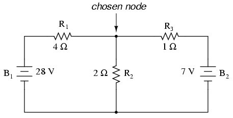
- Node
- A node is a junction, connection or terminal within a circuit were two
or more circuit elements are connected or joined together giving a
connection point between two or more branches. A node is indicated by a
dot.

- Branch

Example:
- Loop
- A loop is a simple closed path in a circuit in which no circuit element or node is encountered more than once.

Example:

Kirchhoff's circuit laws

Here, the 3 currents entering the node, I1, I2, I3 are all positive in value and the 2 currents leaving the node, I4 and I5 are negative in value. Then this means we can also rewrite the equation as;


Kirchhoff's circuit laws
- are two equalities that deal with the current and potential difference (commonly known as voltage) in the lumped element model of electrical circuits. They were first described in 1845 by German physicist Gustav Kirchhoff. This generalized the work of Georg Ohm and preceded the work of Maxwell. Widely used in electrical engineering, they are also called Kirchhoff's rules or simply Kirchhoff's laws.
Kirchoffs First Law – The Current Law, (KCL)
Kirchoffs Current Law or KCL, states that the “total current or charge entering a junction or node is exactly equal to the charge leaving the node as it has no other place to go except to leave, as no charge is lost within the node“. In other words the algebraic sum of ALL the currents entering and leaving a node must be equal to zero, I(exiting) + I(entering) = 0. This idea by Kirchoff is commonly known as the Conservation of Charge.Kirchoffs Current Law
Here, the 3 currents entering the node, I1, I2, I3 are all positive in value and the 2 currents leaving the node, I4 and I5 are negative in value. Then this means we can also rewrite the equation as;
I1 + I2 + I3 – I4 – I5 = 0
The term Node in an electrical circuit generally
refers to a connection or junction of two or more current carrying paths
or elements such as cables and components. Also for current to flow
either in or out of a node a closed circuit path must exist. We can use
Kirchoff’s current law when analysing parallel circuits.Kirchoffs Second Law – The Voltage Law, (KVL)
Kirchoffs Voltage Law or KVL, states that “in any closed loop network, the total voltage around the loop is equal to the sum of all the voltage drops within the same loop” which is also equal to zero. In other words the algebraic sum of all voltages within the loop must be equal to zero. This idea by Kirchoff is known as the Conservation of Energy.Kirchoffs Voltage Law
Learnings:
- node is a two or more branches are connected at a point then that point.
- loop is a closed path in a circuit
- Branch a single element with its terminals
