Sunday, February 22, 2015

Source Transformation 

The source transformation of a circuit is the transformation of a power source from a voltage source to a current source, or a current source to a voltage source.
In other words, we transform the power source from either voltage to current, or current to voltage. 

Source transformation 

Independent current sources can be turned into independent voltage sources, and vice-versa, by methods called "Source Transformations." These transformations are useful for solving circuits.

Voltage Source Transformation

We will first go over voltage source transformation, the transformation of a circuit with a voltage source to the equivalent circuit with a current source.
In order to get a visual example of this, let's take the circuit below which has a voltage source as its power source:

Voltage Source Transformation
Using source transformation, we can change or transform this above circuit with a voltage power source and a resistor, R, in series, into the equivalent circuit with a current source with a resistor, R, in parallel, as shown below:
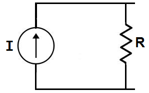
Current Source Transformation
We transform a voltage source into a current source by using ohm's law. A voltage source can be changed into a current source by using ohm's formula, I=V/R.

Example

Let's do an actual example to demonstrate the mathematics of ohm's law, using the circuit shown below:
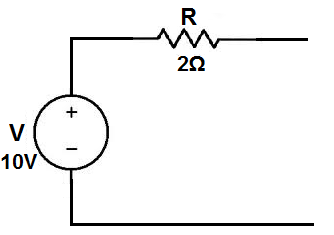
Voltage source transformation example
Here, we have a circuit with a voltage source of 10V with a resistor in series of 2Ω.
To calculate what the equivalent current source would be, we calculate it using the formula: I=V/R, which is I= 10V/2Ω= 5A. So the equivalent circuit would be:
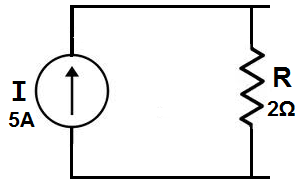
Current source transformation example
The new power source is now a 5A current source. The resistor value, however, as with all source transformations stays the same. The only thing that changes is it is now in parallel for a current source transformation.
Try out our calculator below. With this calculator, you can try out as many examples as you want. The calculator does source transformations and presents the new circuits with the new values.

Current Source Transformation

We will now go over current source transformation, the transformation of a circuit with a current source to the equivalent circuit with a voltage source.
In order to get a visual example of this, let's take the circuit below which has a current source as its power source:
Current Source Transformation
Using source transformation, we can change or transform this above circuit with a current power source and a resistor, R, in parallel, into the equivalent circuit with a voltage source with a resistor, R, in series, as shown below:
voltage source transformation
We transform a current source into a voltage source by using ohm's law. A voltage source can be changed into a current source by using ohm's formula, V= IR.

Example

Let's do an actual example to demonstrate the mathematics of ohm's law, using the circuit shown below:
Current source transformation example
Here, we have a circuit with a current source of 2A with a resistor in parallel of 3Ω.
To calculate what the equivalent current source would be, we calculate it using the formula: V= IR, which is V= 2A*3Ω = 6V. So the equivalent circuit would be:
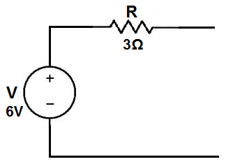
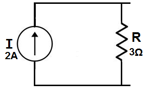
Voltage source transformation example

The new power source is now a 6-volt voltage source. The resistor value, however, again, as with all source transformations stays the same. The only thing that changes is it is now in series for a voltage source transformation.
Again, you can try as many examples as you would like if our calculators below, which do source transformations.

Some Learnings:

In Voltage Source

This voltage source transformation calculator transforms the above circuit with a voltage source and resistor in series into the equivalent circuit with a current source with a resistor in parallel.
The value of the current source is calculated according to ohm's law, I=V/R, current= 
voltage/resistance

The value of the power source will be different; however, the resistor value always remains unchanged.  

In Current Source

This current source transformation calculator transforms the above circuit with a current source and resistor in parallel into the equivalent circuit with a voltage source with a resistor in series.
The value of the voltage source is calculated according to ohm's law, V= IR, voltage= current * resistance

The value of the power source will be different; however, the resistor value, just as with voltage source transformation, always remains unchanged.


Superposition Theorem

Superposition theorem is one of those strokes of genius that takes a complex subject and simplifies it in a way that makes perfect sense. A theorem like Millman's certainly works well, but it is not quite obvious why it works so well. Superposition, on the other hand, is obvious.
The strategy used in the Superposition Theorem is to eliminate all but one source of power within a network at a time, using series/parallel analysis to determine voltage drops (and/or currents) within the modified network for each power source separately. Then, once voltage drops and/or currents have been determined for each power source working separately, the values are all “superimposed” on top of each other (added algebraically) to find the actual voltage drops/currents with all sources active. 

Another prerequisite for Superposition Theorem is that all components must be “bilateral,” meaning that they behave the same with electrons flowing either direction through them. Resistors have no polarity-specific behavior, and so the circuits we've been studying so far all meet this criterion.

The Superposition Theorem finds use in the study of alternating current (AC) circuits, and semiconductor (amplifier) circuits, where sometimes AC is often mixed (superimposed) with DC. Because AC voltage and current equations (Ohm's Law) are linear just like DC, we can use Superposition to analyze the circuit with just the DC power source, then just the AC power source, combining the results to tell what will happen with both AC and DC sources in effect. For now, though, Superposition will suffice as a break from having to do simultaneous equations to analyze a circuit.

Learnings:
  • The Superposition Theorem states that a circuit can be analyzed with only one source of power at a time, the corresponding component voltages and currents algebraically added to find out what they'll do with all power sources in effect.
  • To negate all but one power source for analysis, replace any source of voltage (batteries) with a wire; replace any current source with an open (break).


Thevenin's Theorem

Thevenin's Theorem states that it is possible to simplify any linear circuit, no matter how complex, to an equivalent circuit with just a single voltage source and series resistance connected to a load. The qualification of “linear” is identical to that found in the Superposition Theorem, where all the underlying equations must be linear (no exponents or roots). If we're dealing with passive components (such as resistors, and later, inductors and capacitors), this is true. However, there are some components (especially certain gas-discharge and semiconductor components) which are nonlinear: that is, their opposition to current changes with voltage and/or current. As such, we would call circuits containing these types of components, nonlinear circuits

"Steps to follow for Thevenin's Theorem"
  • (1) Find the Thevenin source voltage by removing the load resistor from the original circuit and calculating voltage across the open connection points where the load resistor used to be.
  • (2) Find the Thevenin resistance by removing all power sources in the original circuit (voltage sources shorted and current sources open) and calculating total resistance between the open connection points.
  • (3) Draw the Thevenin equivalent circuit, with the Thevenin voltage source in series with the Thevenin resistance. The load resistor re-attaches between the two open points of the equivalent circuit.
  • (4) Analyze voltage and current for the load resistor following the rules for series circuits.

Let's start by drawing a general circuit consisting of a source and a load, as a block diagram:
General Source-Load Circuit.svg
Let's say that the source is a collection of voltage sources, current sources and resistances, while the load is a collection of resistances only. Both the source and the load can be arbitrarily complex, but we can conceptually say that the source is directly equivalent to a single voltage source and resistance (figure (a) below).
Thevenin Equivalent.svg
Thevenin Equivalent Under Test.svg
(a) (b)
We can determine the value of the resistance Rs and the voltage source, vs by attaching an independent source to the output of the circuit, as in figure (b) above. In this case we are using a current source, but a voltage source could also be used. By varying i and measuring v, both vs and Rs can be found using the following equation:
v=v_s+iR_s \,
There are two variables, so two values of i will be needed.We can easily see from this that if the current source is set to zero (equivalent to an open circuit), then v is equal to the voltage source, vs. This is also called the open-circuit voltage, voc.
This is an important concept, because it allows us to model what is inside a unknown (linear) circuit, just by knowing what is coming out of the circuit. This concept is known as Thévenin's Theorem after French telegraph engineer Léon Charles Thévenin, and the circuit consisting of the voltage source and resistance is called the Thévenin Equivalent Circuit.